 Variables
Variables
Variables
Send/read value
Address monitoring
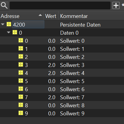
Persistent variables
Automatic linking
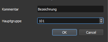
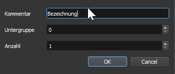
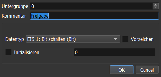
| Subgroup |
Number of the subgroup |
| Comment |
Any comment |
| Data type |
The data types are divided into so-called EIS
types, which are derived from KNX. |
| Sign |
Use sign |
KNX OptionsThe following options are only visible if the main group is in the range between 0 and 31: |
|
| Read on startup |
During controller start-up a read
request is sent to the group address. The read flag must be set in
the ETS for this. |
| Read cyclically |
Here an interval in seconds can be
specified in which the variable is read cyclically. |
| Connected
group addresses |
Here further group addresses can be
added which should be connected to this variable.
Connected means that when one of the connected group addresses
changes, this variable is set to the same value. |
Via the context menu of a variable (right mouse button), Send/read value can be used to manually send or read the current value of the group address. The entry is only active when a connection to the controller exists (operating mode).
Address monitoring lets you combine any variables into groups and observe them together. The dialog is opened via the context menu of a variable (right mouse button – Address monitoring…, directly below Send/read value) and stays open non-modally, so you can continue working in parallel.
Additional variables are dragged from the variable window into the table via drag & drop. Each row shows the address, comment and the current value. While a connection to the controller exists, the value is updated continuously.
Using the + and − buttons, several groups can be created or deleted as separate tabs. When creating a new group, a name is requested so that the tabs can be given meaningful names.
Each row also contains a button that opens the Send/read value dialog for the respective address.
The assembled groups are saved automatically when the dialog is closed and restored on the next start.
All variables are saved every hour by default. This is sufficient for the vast majority of use cases. The persistent variables area has a special position here. These are saved after a change 10 seconds later. Important: The controller is equipped with a flash memory that cannot be written to as often as required. Therefore, this area must not be used for values which change continuously. Continuously saving persistent values shortens the lifetime of the flash memory and leads to a defect or loss of data.
With this function, variables can be linked automatically where this makes sense. For example, the Blind control element has 6 links, in this case only one variable has to be dragged onto the element in order to link all of them automatically. This works for the control elements as well as for the Shutter and Dimmer function blocks.
A training video on this topic can be viewed at the following link: Training video
To use this feature, the variables must always be created in the same way in the ETS.
To do this, the variable must be dragged onto the control element with the Alt key pressed. This variable is linked as the first address and the text in brackets is taken over as heading. With Alt+Shift only the variables without text are linked.
Example comment in variable "1L2 (living room left)", if this variable is dragged onto the Blinds universal control element, "living room left" is taken over as heading and linked as the first address. Depending on the setting, subsequent addresses are also linked automatically.
Right-click on a variable and select Settings - automatic links, in the following dialog the settings for automatic linking can be changed.
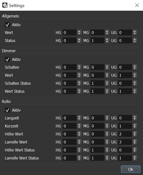
The settings are divided into three areas:
In the settings dialog the offsets for the subsequent addresses are now defined. The first address is normally always set to 0/0/0 and is only included for the overview. If an address is now linked, the offset is added to it and then linked.
Example dimmer, the following addresses were created:
Switch: 0/0/1
Value: 0/0/2
Switch status: 0/1/1
Value status: 0/1/2
In this example the offsets must be set as follows:
Switch: 0/0/0 (0/0/0+0/0/1 results in 0/0/1)
Value: 0/0/1 (0/0/1+0/0/1 results in 0/0/2)
Switch status: 0/1/0 (0/1/0+0/0/1 results in 0/1/1)
Value status: 0/1/1 (0/1/1+0/0/1 results in 0/1/2)
The offsets are therefore always added to the first address and then linked. This means that only the first address has to be linked, the others are linked automatically.