 Heating Curve
Heating Curve
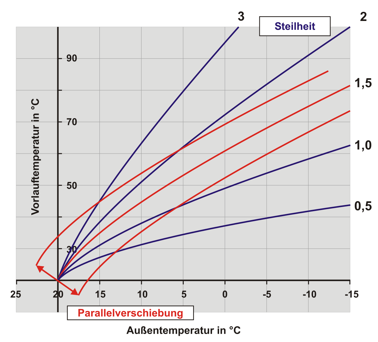
Heating CurveThis block automatically calculates the correct flow temperature (the water temperature sent to the mixer) – matched to the current outside temperature. The basic idea: the colder it is outside, the more heating is needed; the hotter it is outside, the more cooling. Nobody has to readjust by hand.
At around 20 °C outside temperature the flow is exactly at the room setpoint (neutral point). Only below it (heating) or above it (cooling) does it deviate.
The slope determines how strongly the flow reacts to a change of the outside temperature – comparable to a sensitivity or gain. A larger value makes the curve steeper, a smaller one flatter.
Heating example – room setpoint 22 °C, at +5 °C outside temperature:
| Slope | 0.25 | 0.5 | 1.0 |
| Flow | approx. 26 °C | approx. 31 °C | approx. 39 °C |
Same outside temperature, but the larger the slope, the warmer the flow. For cooling it is the other way round: a larger slope → colder flow at the same outside temperature (more cooling).
Important: The slope always has to be entered as a positive value – for the cooling curve as well. The block itself takes care of reversing heating/cooling. A negative value would mirror the curve and cause exactly the opposite. The controller therefore does not permit negative values: it continues to calculate with the absolute value and issues an error message with block and value in the diagnostics (program). The value itself is not changed – it has to be corrected at the block.
Tip: Usual values are small (heating approx. 0.2–1.5, cooling approx. 0.1–0.3). A very large value (e.g. 5) makes the flow immediately hit the min/max limit, so it then seems as if „nothing changes anymore“.
The parallel shift raises or lowers the entire curve by a fixed amount – independent of the outside temperature. It is simply added to the calculated flow temperature.
Important: it works the same in both operating modes (it is not inverted):
So consistently: „+ = warmer, - = colder“. This corresponds to the „level“ setting of common heat pump controllers.
Use: Are the rooms uniformly – i.e. at every outside temperature – a little too cool? Then increase the parallel shift instead of changing the slope. Rule of thumb: approx. 3 °C of flow produce roughly 1 °C in the room.
These parameters limit the result at the bottom and top (protective limits):
In hot weather the cooling curve lowers the flow below the room setpoint. It would be wrong if the flow were above the room setpoint in the heat – that would heat instead of cool. The following example shows the calculation step by step.
Given values:
| Room setpoint (RS) | 22 °C |
| Outside temperature (AT) | 32 °C |
| Cooling enable (FK) | 1 (cooling curve active) |
| Cooling curve / slope (KK) | 0.2 |
| Cooling parallel shift (KP) | +1 °C |
| Cooling flow minimum / maximum | 18 °C / 25 °C |
| Cooling room sensor influence | 0 % |
Calculation:
| Step | Calculation | Result |
| 1. Distance from the neutral point (20 °C), weighted twice | (32 − 20) × 2 | 24 |
| 2. Curvature factor from setpoint and outside temperature | 22 to the power of (32 / (320 − 4 × 32)) = 22 to the power of 0.167 | approx. 1.67 |
| 3. Reduction below the setpoint | 0.55 × 0.2 × 1.67 × 24 | approx. 4.4 K |
| 4. Flow from the curve | 22 − 4.4 | 17.6 °C |
| 5. Add the parallel shift | 17.6 + 1 | 18.6 °C |
| 6. Limit to minimum/maximum | 18.6 is between 18 and 25 | 18.6 °C at output VS |
With room sensor influence: If the cooling room sensor influence were additionally set to 50 % and the room were 2 K too warm at 24 °C, the deviation setpoint − actual = 22 − 24 = −2 results in a correction of −2 / 100 × 50 = −1 K. The flow therefore drops to 17.6 °C and is limited to 18.0 °C by the cooling minimum – so the dew point protection takes effect before the control does.
The same calculation for other slopes (room setpoint 22 °C, without parallel shift, cooling minimum 18 °C):
| Cooling curve slope | 0.1 | 0.2 | 0.5 |
| Outside temperature 28 °C | approx. 20.7 °C | approx. 19.3 °C | 18.0 °C (limited) |
| Outside temperature 32 °C | approx. 19.8 °C | 18.0 °C (limited) | 18.0 °C (limited) |
Important: The cooling curve has to be set considerably flatter than the heating curve – usual values are approx. 0.1–0.3. The usable range between room setpoint and dew point is only a few kelvin; with larger slopes the flow immediately hits the cooling minimum and the curve then acts like a fixed temperature.
Unconnected inputs are not automatically treated as 0 – the block uses reasonable substitute values. The following overview applies to both blocks (heating curve and heating/cooling curve).
| Input | not connected | connected with value 0 |
| FG Enable | enabled | blocked, output 0 |
| RS Room setpoint | 22 °C | 20 °C |
| RT Room temperature | 0 °C | 0 °C |
| AT Outside temperature | 0 °C | 0 °C |
| HK Heating curve / KK Cooling curve | 0.5 | 0.1 (0 cannot be calculated) |
| HP / KP / PV Parallel shift | 0 (no shift) | 0 (no shift) |
| FK Cooling enable | heating curve is calculated | heating curve is calculated |
| AA Outside shutdown (heating curve only) | no shutdown | shutdown from 1 °C outside temperature |
The room setpoint has a double effect: it is the starting point of the curve (flow at 20 °C outside temperature) and it also enters the curvature factor. A typical case from practice: after a restart the setpoint (e.g. a KNX address) has no value yet and is therefore 0 – the calculation then uses 20 °C instead of the desired 22 °C, so the flow is a few kelvin too low until the setpoint arrives. Have the setpoint sent actively after the start.
Rule: Only set a room sensor influence greater than 0 if the room temperature input is actually connected and supplies a plausible value. Otherwise leave the room sensor influence at 0 and additionally cover a sensor failure via the enable input.
If the flow stays constant in cooling mode or even rises, it is almost always due to one of the following points:
The representation below uses the same formula as the controller. The sliders show how slope, parallel shift, limits and room sensor influence take effect. The solid line is the value at output VS, the dashed line shows the calculation before the limitation by minimum and maximum. The other operating mode is drawn faintly alongside.
| With
this function block a heating curve is calculated. |
Inputs |
||
| FG |
Enable |
Enable. If this input is not
assigned, the calculation is automatically enabled. Without enable
the flow setpoint 0 is output. If this is connected to the logic
Mixer, it closes at setpoint 0 and switches off the
heating circuit pump. |
| RS |
Room setpoint* |
Setpoint for the room temperature to be
reached. If this input is not connected, the calculation uses
22 °C. If it is connected and supplies 0 or a negative
value, the calculation uses 20 °C - with a setpoint of 0 °C the
curve could not be calculated sensibly. |
| RT |
Room temperature |
Room temperature. This input is
optional. When this input is assigned and a value greater than 0 is set
in the parameter "Room sensor influence", the flow temperature is
increased at too low a room temperature or
decreased at too high a room temperature. If this input is not
connected or supplies 0, the calculation uses 0 °C -
there is no substitute value here. In this case the parameter "Room
sensor influence" has to be 0, otherwise the flow is heavily
falsified. |
| AT |
Outside temperature* |
Outside temperature. |
| HK |
Heating curve/slope* |
Slope of the heating curve. It
influences the calculation of the flow setpoint temperature based on the
outside temperature and always has to be entered as a positive
value (usual values 0.2 to 1.5): the larger the value, the warmer the flow
at low outside temperatures. A negative value would mirror the curve
and is therefore not permitted: the controller calculates with the absolute
value (-0.4 becomes 0.4) and reports the value as an error in the diagnostics
(program). If this input is not connected, the calculation uses 0.5; the
value 0 is replaced by 0.1. |
| PV |
Parallel shift |
This value is added to the calculated
flow setpoint temperature. |
| AA | Outside shutoff | Outside shutoff. If this input is connected, from this temperature on the output is set to 0. The hysteresis is 1 degree. If the temperature is for example set to 20 degrees, the outside shutoff becomes active at 21 degrees and inactive at 19 degrees. |
Outputs |
||
| VS |
Flow
setpoint |
Calculated flow setpoint - is
usually connected to the logic Mixer. |
| AA | Outside shutoff active | Output 1 when outside shutoff is active. |
Parameters |
||
| Flow
minimum |
Flow minimum. The calculated
setpoint temperature is limited to this minimum. |
|
| Flow
maximum |
Flow maximum. The calculated setpoint temperature is limited to this maximum. Important: Especially with underfloor heating a limit should be specified here. With underfloor heating it must also always be checked whether a thermal safety valve is present. With improper parameterization or hardware faults damage to the system can otherwise occur. | |
| Room sensor influence |
A room sensor influence in
percent can be specified here. If a value is connected at the input
Room temperature, the setpoint/actual value deviation is added proportionally to the
flow setpoint. |
|
Inputs |
||
| FG |
Enable
total |
Enable of the calculation. If this
input is not assigned, the calculation is automatically enabled.
Without enable the flow setpoint 0 is output. If this is connected to
the logic Mixer, it closes at setpoint 0 and
switches off the heating circuit pump. |
| RS |
Room setpoint* |
Setpoint for the room temperature to be
reached. If this input is not connected, the calculation uses
22 °C. If it is connected and supplies 0 or a negative
value, the calculation uses 20 °C - with a setpoint of 0 °C the
curve could not be calculated sensibly. |
| RT |
Room temperature |
Room temperature. This input is
optional. When this input is assigned and a value greater than 0 is set
in the parameter "Room sensor influence", the flow temperature is
increased at too low a room temperature or
decreased at too high a room temperature. If this input is not
connected or supplies 0, the calculation uses 0 °C -
there is no substitute value here. In this case the parameter "Room
sensor influence" has to be 0, otherwise the flow is heavily
falsified. |
| AT |
Outside temperature* |
Outside temperature. |
| HK |
Heating curve* |
Slope of the heating curve. It
influences the calculation of the flow setpoint temperature based on the
outside temperature and always has to be entered as a positive
value (usual values 0.2 to 1.5): the larger the value, the warmer the flow
at low outside temperatures. A negative value would mirror the curve
and is therefore not permitted: the controller calculates with the absolute
value (-0.4 becomes 0.4) and reports the value as an error in the diagnostics
(program). If this input is not connected, the calculation uses 0.5; the
value 0 is replaced by 0.1. |
| HP |
Heating
parallel shift |
This value is added to the calculated
flow setpoint temperature. |
| FK |
Cooling
enable |
Cooling enable. If this input
is not assigned, the heating curve is always calculated. On enable
the cooling curve is output at the output instead of the heating curve. |
| KK |
Cooling curve |
Slope of the cooling curve. It influences the calculation of the flow setpoint temperature based on the outside temperature and - just like the heating curve - always has to be entered as a positive value (usual values 0.1 to 0.3): the larger the value, the colder the flow at high outside temperatures. A negative value would mirror the curve (the flow would rise with rising outside temperature) and is therefore not permitted: the controller calculates with the absolute value (-0.4 becomes 0.4) and reports the value as an error in the diagnostics (program). If this input is not connected, the calculation uses 0.5; the value 0 is replaced by 0.1. |
| KP |
Cooling
parallel shift |
This value is added to the calculated flow setpoint temperature. |
Outputs |
||
| VS |
Flow
setpoint |
Calculated flow setpoint - is
usually connected to the logic Mixer. |
Parameters |
||
| Heating
flow minimum |
Flow minimum heating curve. The
calculated setpoint temperature is limited to this minimum. |
|
| Heating
flow maximum |
Flow maximum heating curve. The calculated setpoint temperature is limited to this maximum. Important: Especially with underfloor heating a limit should be specified here. With underfloor heating it must also always be checked whether a thermal safety valve is present. With improper parameterization or hardware faults damage to the system can otherwise occur. | |
| Heating
room sensor influence |
A room sensor influence in
percent can be specified here. If a value is connected at the input
Room temperature, the setpoint/actual value deviation is added proportionally to the
flow setpoint. |
|
| Cooling flow minimum | Flow minimum cooling curve. The
calculated setpoint temperature is limited to this minimum. Important:
A limit should always be specified here so that with
improper parameterization no damage from condensation
can occur. |
|
| Cooling flow maximum | Flow maximum cooling curve. | |
| Cooling room sensor influence | A room sensor influence in percent can be specified here. If a value is connected at the input Room temperature, the setpoint/actual value deviation is added proportionally to the flow setpoint. In cooling mode this means: if the room is too warm the flow is lowered (more cooling), if it is too cool the flow rises. | |