 Controller
Standard Controller
Standard
Controller
Standard Controller
Standard| This description describes the web interface of the controller. The complete documentation can be found in the hardware documentation. See also the data sheet as PDF. |
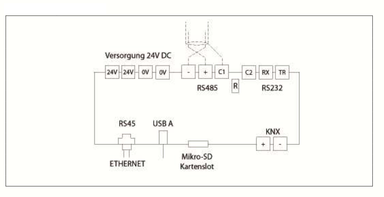
Important: The micro SD card slot is only used to update the firmware of the IO modules. No SD card may be inserted during operation, otherwise the IO board will not boot; as a consequential error the serial number cannot be read and the error "license invalid" appears. How to recognise this situation on the MODE LED is described under MODE LED: SD card in the slot.
The controller has a USB port to which serial USB adapters or USB sticks
can be connected. Important: When using serial USB adapters, you
should not use them for critical components. The operating system of the
controller does not support all USB adapters and USB sticks, therefore
products from brand manufacturers are recommended. In general, USB
components are used at your own risk.
Tip: The controller can be reset to factory settings with the reset button on the controller. To do this, the reset button must be pressed for 30 seconds until the LED stops flashing. Then release the reset button, the controller will then restart automatically.
The controller consists of two assemblies: the IO board, which handles the inputs and outputs, and the CPU board, on which the runtime runs. The MODE LED belongs to the IO board, the RUN LED is driven by the runtime on the CPU board. The two LEDs therefore indicate different things - which is exactly what makes them the most important tool for troubleshooting on site.
The MODE LED consists of a red and a green LED. The following sequence takes place when switching on:
| 1x
short red (0.2 seconds) |
The bootloader of the IO board
starts. |
| 2x
red, then 1x green |
Normal start of the system: flashing
red twice (different duration) and green once. The IO board is now
ready for operation. |
| MODE
LED stays dark |
The CPU board is booting. This step
takes considerably longer than the start of the IO board, depending
on the image a few minutes. During this time the RUN LED does not
flash yet either. |
| green
lights up briefly, RUN LED starts to flash |
The runtime has started and reads the
information from the IO board. Both LEDs react at the same time -
this confirms that the CPU board and the IO board are working
together. |
| green
during operation |
Indicates the communication with the
IO board, see the following section. |
| red
during operation |
Communication error with the IO
modules. |
The green MODE LED indicates the communication with the IO board. It flashes because the runtime reads information from the IO board. What matters here is what has been configured in the project:
Target state during operation: The red MODE LED must not light up. The green MODE LED can be off, lit or flashing, depending on the program.
If a card is inserted in the externally accessible micro SD slot next to the Ethernet socket when switching on, the bootloader starts instead of the application and looks for the file R02_FW.bin on the card. The application of the IO board then does not start, so the controller does not boot completely. This situation can be recognised on the MODE LED:
| 1x
long red (3 seconds) |
A card is inserted but the file
R02_FW.bin is not on it. The device remains in the bootloader. |
| red
flashing fast / continuously |
A firmware update has been completed
successfully, the device is waiting for the card to be removed. If
the card is not removed, a new update starts every time the device
is switched on. |
| 2x
short red (0.2 seconds) |
The bootloader restarts due to a
problem, for example wrong file size, verification error or an error
while writing to the memory. |
As a consequential error the serial number of the IO board cannot be read, and the Studio reports "license invalid". If you see this message, the first thing to check is the SD card slot.
Remedy: Disconnect the controller from the power supply, remove the card and switch it on again. The externally accessible slot is intended exclusively for the firmware update of the IO board; the complete list of flash codes can be found under Firmware update IO board. Not to be confused with the SD card on the CPU board, which holds the operating system and the license, see Re-flashing the SD card.
The RUN LED is driven by the runtime on the CPU board. If the RUN LED is flashing, the controller and thus the runtime is running. This is the most important sign of life of the controller.
After switching on, the LED remains quiet until the CPU board has booted, which can take a few minutes depending on the image. With the first flash the green MODE LED also lights up briefly.
The flashing rate additionally indicates the state of the VPN connection:
| fast
rate (changing about every 0.5 seconds) |
The runtime is running and the VPN
connection is established. |
| slow
rate (changing about every 1.5 seconds) |
The runtime is running, but there is
no VPN connection. If VPN is not switched on, this is the normal
case. |
| LED
permanently on or off |
The runtime is not running. First
wait a few minutes, then check the power supply and restart the
controller. |
This makes it possible to narrow down a remote access problem on site without having to connect a PC.
Note: When resetting to factory settings, the LED stops flashing after 30 seconds, see Commissioning. In this case the LED stopping is not an error but the acknowledgement of the reset button.
There are two LEDs on the network socket. One of them indicates the established connection to the switch or router and lights up permanently, the other indicates the data traffic and flickers irregularly. These LEDs are driven by the hardware and also light up when the runtime is not running.
If the controller cannot be reached or does not work as expected, it is best to work from the outside in:
The following table summarises the most common symptoms:
| No
LED is lit |
There is no supply voltage. Check the
24V DC supply and the terminals. |
| RUN
LED does not flash, is permanently on or off |
The runtime is not running or the CPU
board has not booted. After switching on, wait a few minutes, then
disconnect the controller from the power supply and restart it. If
this does not help, the operating system on the SD card of the CPU
board has to be checked, see Re-flashing
the SD card. |
| RUN
LED flashes slowly, remote access does not work |
There is no VPN connection. Check
whether VPN is switched on in the web interface (see Enable/disable
VPN) and whether the controller reaches the Internet under Test
Internet connection. Further information under VPN. |
| RUN
LED flashes, the Studio does not find the controller |
The runtime is running, the problem
is in the network. The most common cause is DHCP without a DHCP
server in the network. Connect via the static IP address
172.31.1.100 and switch DHCP off, see Network
settings. |
| Red
MODE LED is lit during operation |
Communication error with the IO
modules. Check that the modules are properly seated on the DIN rail
and compare the configuration in the Studio with the modules that
are actually fitted. |
| Green
MODE LED stays off |
Normal if no IO modules are
configured in the project or if only output modules without any
change are present. If modules with inputs are configured, the green
LED must light up continuously. If it stays off in that case, check
the configuration in the Studio and the seating of the modules. |
| MODE
LED flashes 1x long red (3 seconds) at start |
There is an SD card in the externally
accessible slot on which the file R02_FW.bin is missing. Disconnect
the controller from the power supply and remove the card. |
| MODE
LED flashes red quickly after an update |
The firmware update is complete and
the SD card has to be removed. Otherwise a new update starts every
time the device is switched on. |
| The
Studio reports "license invalid" |
The serial number of the IO board
cannot be read, usually because an SD card is inserted in the slot
and the IO board has therefore not booted. Remove the card and
restart the controller. If the error persists, please contact our
support. |
| No
LED is lit on the network socket |
There is no connection at cable
level. Check the network cable, the port on the switch and the
remote station. |
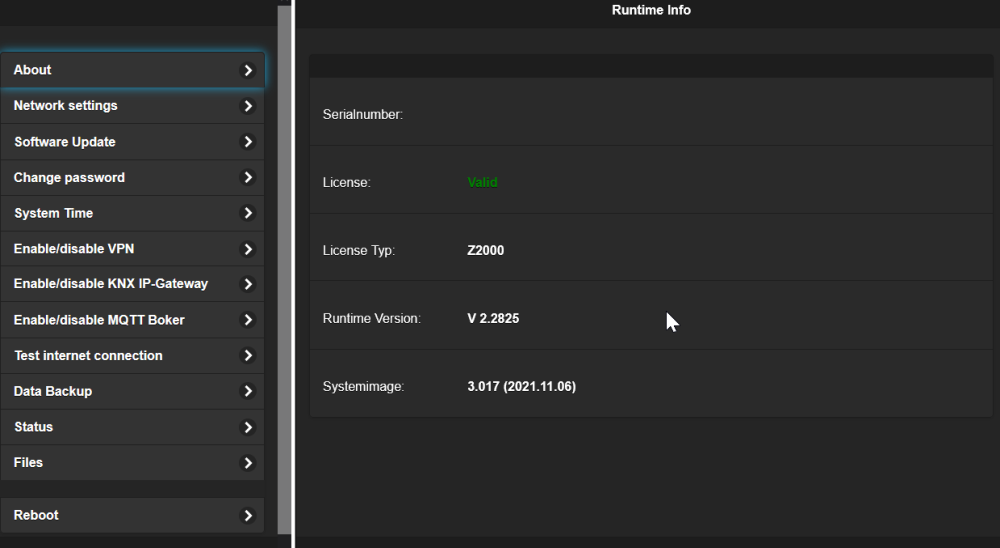
| Serialnumber |
The serial number is used to
uniquely identify the controller. This is not the same serial
number that is printed on the controller. This number is a
so-called GUID; since this number is also used for service access,
it is generated separately for each controller and cannot be
guessed by counting up. |
| License |
If the controller is licensed,
"Valid" is displayed here in green, otherwise "Not valid" in red. |
| License Typ |
Type of the license. |
| Runtime Version |
Version of the runtime |
| Systemimage |
Version of the system image |
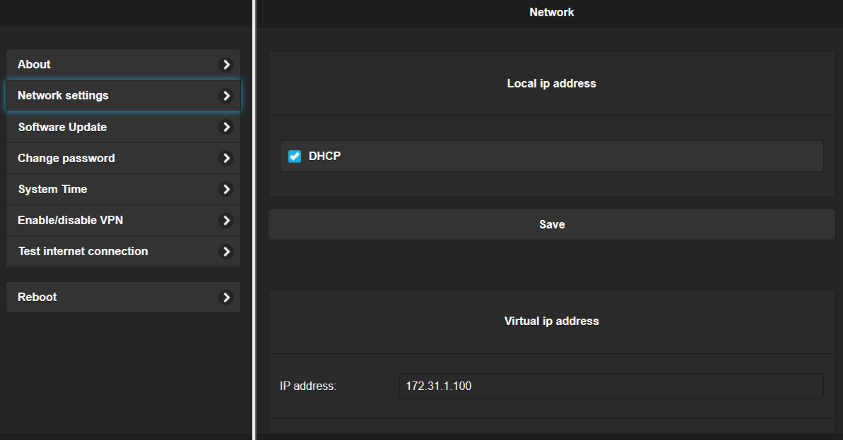
| DHCP |
Switch between static IP address and
DHCP. |
| IP Address |
Static IP address |
| Mask |
Network mask |
| Gateway |
Default gateway |
| DNS 1 / DNS 2 |
DNS server. Two DNS servers can be
specified. |
| IP Address | Static IP address |
| Mask | Network mask |
| Gateway(optional) | Default gateway. If no gateway is
available for the virtual IP (for example if no VLAN is used), the
field must be left empty; this is also the default setting. |
| Route (optional) |
Optionally, a route can be entered here if the virtual IP address is used as a backbone. E.g.: route add -net 172.31.2.0 netmask 255.255.255.0 dev eth0:1 gw 172.31.1.1 |
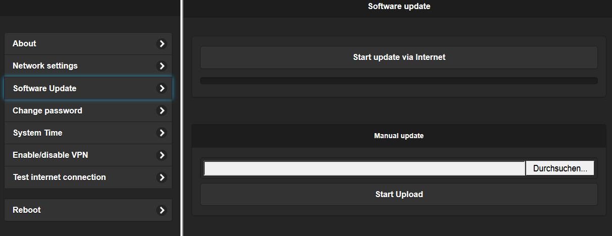
| Start
update via Internet |
This function starts the update via
the Internet. If the controller is connected to the Internet, the
latest version is always loaded via the update server. The VPN does
not have to be active for this. |
| Manual update |
With this function, the runtime can
be installed manually, for example if no Internet is available or
you want to install an older version. To do this, select the update
file and click on "Start Upload". |
| Tip:
Only update the controller if there is a reason to do so, for
example bug fixes or new features. If the system is running without
problems, there is no need for an update. |
|
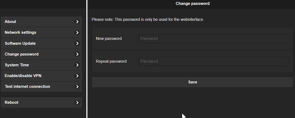
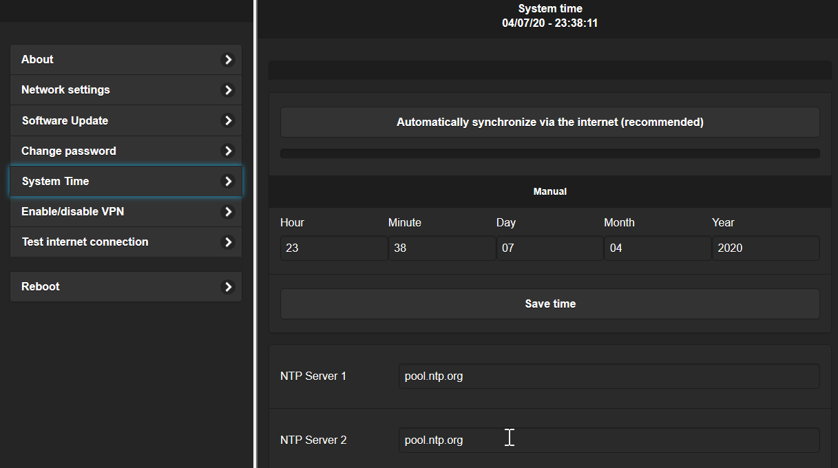
| Automatically
synchronize via internet |
With this option, the system time is
automatically synchronized via the configured NTP servers
(recommended). With "Synchronize via the internet now" the
synchronization can be started manually right away. |
| Manual |
With this function, the system time
can be set manually. Enter the time and date and click on "Save
time". |
| NTP Server |
Alternative NTP servers can be set
here. |
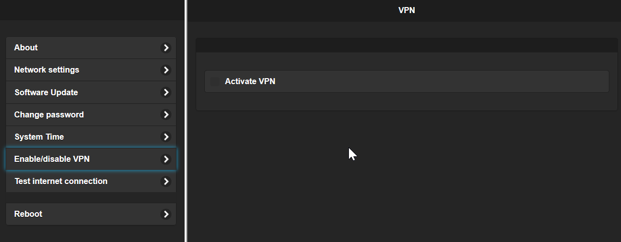
| Activate
VPN |
Activate VPN. After activation, it
may take some time until the connection has been established; you
can check the status on the "Test Internet connection" page. |
Tips:
See also Remote access. |
|
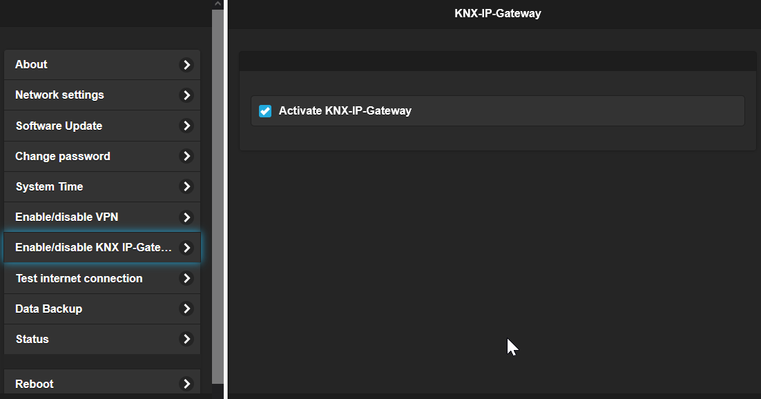
| Activate
KNX-IP-Gateway |
This option activates the internal
KNX IP gateway. This makes it possible to program KNX devices via
the ETS through the controller. The ETS finds the gateway via the
automatic interface search. |
Important:
|
|
| Activate
MQTT Broker |
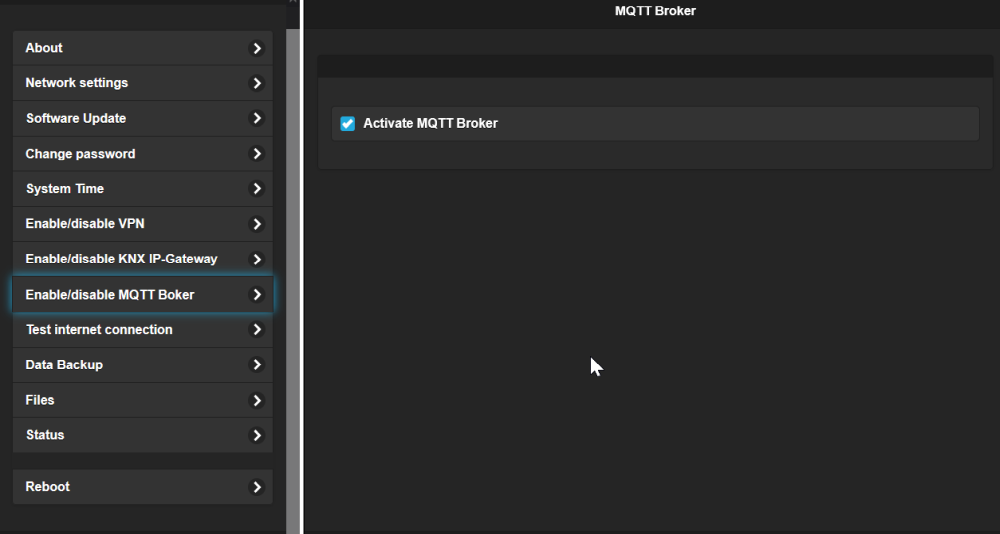
This option activates the internal
MQTT broker. It is used to connect devices that support MQTT to the
controller, for example Shelly devices. This option should only be activated if an industrial memory card is installed in the controller because swapping is activated. In addition, the controller should have an active fan. Industrial memory card and fan are optionally available. |
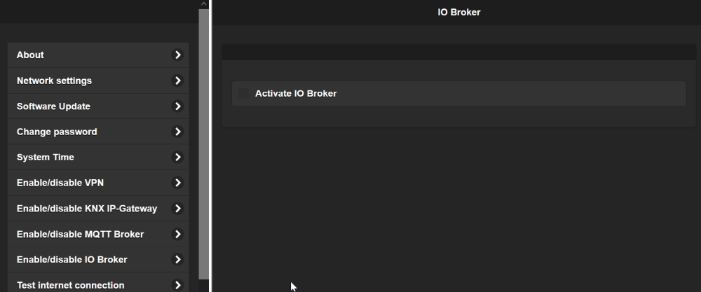
From image version 3.
| Activate
Node Red |
This option activates the NodeRED software. The NodeRED platform
contains many additional interfaces that can be used with uniPRO. The link "Start NodeRED Console" opens the NodeRED user interface (port 1880). See https://nodered.org/ |
Important:
|
|
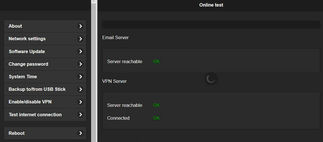
| Email
Server |
Server for sending emails. This test
only tests the manufacturer's server. If an alternative mail server
has been set, it is not tested. |
| VPN Server
reachable |
VPN server basically reachable; this
is the prerequisite for a VPN connection to be established at all. |
| VPN connected |
VPN connection successfully
established. |
| Portal Server |
Server of the online portal for the
data backup reachable. See Data Backup
online Portal. |
On this page, the data of the controller is backed up to a USB stick or restored from it.
| Enable automatic
daily backup |
With this option, a backup of all
data is automatically created on a USB stick. The backup is started
daily at 2 am. The USB stick must be FAT formatted. To test the
function or whether the USB stick is compatible, the backup/restore
should be carried out manually. |
| Save data to USB Stick | Data is saved to the USB stick. |
| Restore Data from USB Stick | Data is restored from the USB stick. |
On this page, the data of the controller is backed up to the manufacturer's online portal or restored from it. A token is required for use; you receive this via the portal. The controller must be connected to the Internet for this; whether the portal server is reachable can be checked on the "Test Internet connection" page.
Important: Please note the disclaimer when using the backup service; the link to it is displayed on the page.
| Enable automatic
daily backup |
With this option, a backup of all
data is automatically transferred to the online portal every day. |
| Token | Access token for the online portal. Enter the token from the portal here and click on "Save". |
| Save data to Portal | Data is saved to the online portal. After a successful backup, the data should be checked on the portal. |
| Restore data from Portal | Data is restored from the online portal. |
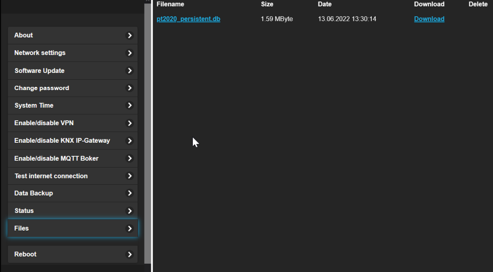
| Files |
In this area, the saved data is
displayed and can be downloaded or deleted. In addition, the project and the persistent data can be loaded onto the controller. The project must be renamed to "pt2020_boot.db" and the persistent data to "pt2020_persistent.db". After the upload, the controller is automatically restarted. |
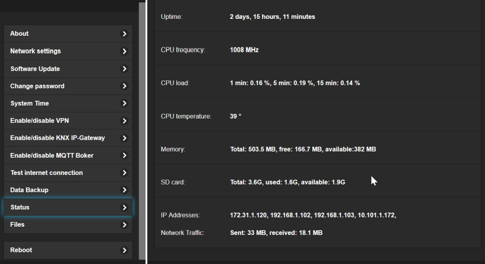
| Status |
In this area, some status
information of the controller is displayed: time since the last
start (uptime), CPU frequency, CPU load, CPU temperature, memory,
usage of the SD card and the current IP addresses. |
The controller can be restarted on this page. To do this, click on "Reboot controller now". The restart takes about one minute, after which the controller can be reached again. A restart is necessary, for example, after changing the network settings.
| Supply voltage | 24V DC +15%, -5% |
| Current consumption | 200mA |
| CPU | ARM quad core up to 1.2 GHz, 512M RAM |
| Interfaces | RS485, RS232, (optional KNX), Ethernet, USB |
| Real-time clock | Real-time clock with battery |
| Housing | 45mm modular system WxHxD: 70x90x58mm |
| Terminals | Plug-in terminals with push-in connection, up to 1.5 mm² |
| Mounting | DIN rail TS35 |
| Ambient temperature | -10...+50°C |
| Protection class | IP20 |
The operating system of the controller is located on an SD card on the CPU board. If this SD card is defective or the system is damaged, a new SD card can be written (flashed) with the image. The following instructions describe step by step how to proceed.
When flashing, the SD card is completely overwritten, and the license and the VPN link are also lost. Therefore, be sure to back up the license before flashing if the controller is still reachable:
Important: If it was not possible to back up the license (for example because the controller no longer starts), the controller must be re-licensed and enabled for VPN by the support after flashing. This is only possible with direct access to the controller. In this case, please contact our support.
If possible, also back up the project and the data of the controller, for example via the web interface with "Data Backup USB" or "Data Backup online Portal" or by loading the project into the Studio.
The persistent values (for example meter readings, setpoints or operating hours) are also stored on the SD card and are lost when flashing. They are not backed up together with the project but in a separate file:
Note: A backup is not possible without a connection to the controller. If the controller no longer starts, the persistent values can only be restored from a backup, see Data Backup USB or Data Backup online Portal.
Important: The controller has an SD card slot that is visible from the outside. This is only for a software update of the IO board, not for the image. The SD card with this image must be inserted in the controller on the CPU board.
Finally, transfer the backed-up data back to the controller and check the settings (network, VPN, time).
The IO board can be updated via the SD card slot on the outside. Important: This update only updates the firmware of the IO board. Not to be confused with updating the runtime, which is updated via the web interface. Normally, updating the IO board is only necessary in exceptional cases, for example if new IO modules have been added that did not exist at the time of delivery.
Excerpt from the hardware manual:
Insert the SD card with the unzipped file R02_FW.bin into the directly accessible micro SD socket next to the Ethernet socket and then supply the device with power; the new software will then be loaded automatically.
1x short red (0.2 sec): start of the bootloader
2x short red (0.2 sec): bootloader restarts due to a problem (wrong bin
file size, verification error, error writing to the memory);
1x red long (3 sec): the R02_FW.bin file cannot be found
red + green lit: memory is being erased
red + green flashing simultaneously: new firmware is being written to the
memory;
red flashing fast / continuously: saving successfully completed, waiting
for the SD card to be removed – this is absolutely necessary, otherwise
a new update would start with every power cycle)
After the application has started, these LEDs are used to indicate communication with the CPU board. A normal start of the system is indicated by flashing red twice (different duration) and green once. The meaning during operation is described under LED.